In the solution explorer under hldll > Header Files > dlls lets create a custom header file to include all our newly created Classes and Functions related to point entities.
For now, that will only cover a static model that doesn’t move (but can animate on the spot).
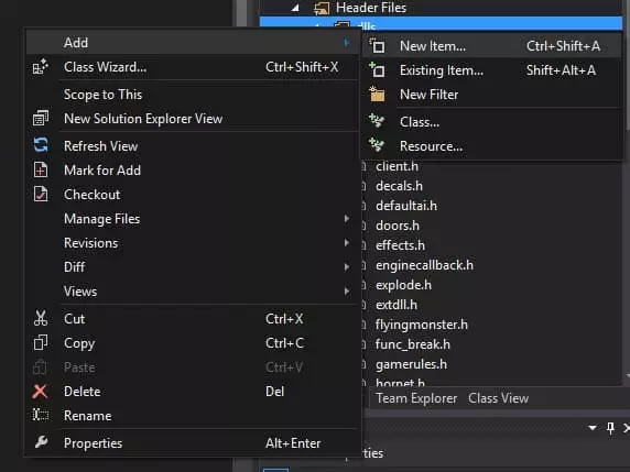
Right-Click on dlls and select Add -> New Item.
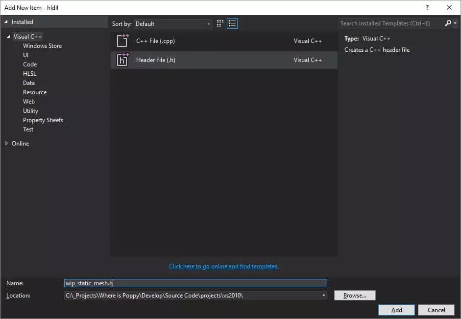
Select Header file and give your file a unique name, I call this file “wip_static_mesh.h” Now let’s add a .cpp file under hldll > Source Files > dlls.
Right-Click on dlls and Select Add -> New Item, this time select C++ File (.cpp) and name it the same way you called your header file with the exception of the extension which should be .cpp “wip_static_mesh.cpp”
Next let’s start preparing what will be the very minimum you will need to get a Static Mesh loading in your Mod.
Header
I typically always start with a block comment at the top which looks something like this.
/******************************
Where is Poppy
February, 2017

wip_static_mesh.h

Static Mesh Loader for the mod
Where is Poppy

*******************************/
I then define the Header file and include any dependencies the class will require.
#ifndef WIP_STATIC_MESH_H
#define WIP_STATIC_MESH_H

#include "extdll.h"		// Required for KeyValueData & Export Parts
#include "util.h"		// Required Consts & Macros
#include "cbase.h"		// Required for inheriting from CBaseAnimating
Next we will create the Class itself and give it a unique name from anything else that has been created in the project so as to avoid conflicts in naming and reference etc.
The class will be called CStaticMesh and it inherits from CBaseAnimating so that we can use some cool functions from it later
class CStaticMesh : public CBaseAnimating
{
private:
	void Spawn(void);
};

#endif
We declare our functions which will be used in the cpp file later.
Spawn: which pretty much spawns our entity in the world when called upon either by other code or a level including it.
Source CPP File
Again starting with a comment block just to keep things orderly.
/******************************
Where is Poppy
February, 2017

wip_custom_point_entities.cpp

contains the source functions
related to custom point entities
for Where is Poppy

*******************************/
Next we include a reference to our header file we created earlier. Since we include all other references in the header file there is no need to #include anything else here.
#include "wip_static_mesh.h"Then we must link our class CStaticMesh to what hammer will recognise it as: “wip_StaticMesh” (this is what we will add to our custom FGD shortly)
LINK_ENTITY_TO_CLASS(wip_StaticMesh, CStaticMesh);Next up is the Spawn function which will take control of adding our mesh to the world.
If we don’t Precache the model the game will hang on start-up so it’s a necessary, step. If you remove the model file or rename it Half-Life will exit on load complaining that its can’t find the model. You can read a little more about precaching here.
Next we set the model itself using the SET_MODEL Macro/function
void CStaticMesh::Spawn(void)
{
	PRECACHE_MODEL((char *)STRING(pev->model));
	SET_MODEL(ENT(pev), STRING(pev->model));
}
That’s all we need on the programming side to get a static mesh loaded into the Game.
Save your Header and CPP file and compile. You should see that everything compiled correctly and a file was copied to your mod directory (if you are following on exactly from my previous tutorial)
Forge Game Data (.fgd)
Let’s create in your text editor of choice a new file called after your mod. In my case I will call it wip.fgd and I will save it to my “WhereIsPoppy_dev” Mod Directory inside the Half-Life Directory.
This is what my wip.fgd file looks like.
// Where is Poppy Forge Game Data
// Cathal McNally
// sourcemodding@gmail.com
// www.sourcemodding.com

// February, 2017

// wip_StaticMesh

@PointClass color(0 255 0) size(-20 -20 -20, 20 20 20) studio() = wip_StaticMesh : "wip_StaticMesh"
[
	model(studio) : "Model"
]
Basically an FGD is a descriptor for Hammer to interface with classes you have created in code. This represents your CStaticMesh Class inside Hammer. In the entity list when we add this FGD to our mod we will see a new entry called “wip_StaticMesh” which reads this Key : Value Data to figure out what options to give the user within hammer.
In this case we will only see a browse dialog for a Model File. We set some other settings such as color and size which correspond to the color and size of the initially placed entity prior to selecting a Model. More on this later.
Save your FGD and let’s fire up JackHammer.
Add our Custom Entity to the Level
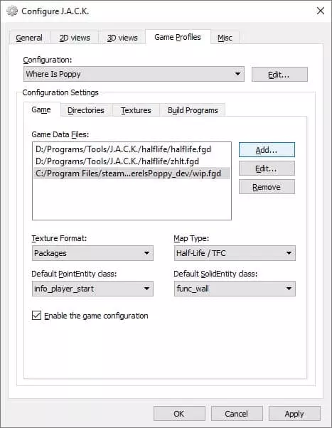
In JackHammer (or any good hammer editor/variant) lets add our custom FGD file under Tools > Options > Select “Game Profiles” > Add..
Open the Map we started working on from the previous tutorial “Test_01.map”. It should be available in Jackhammers, recent file list.
Select the Point Entity Tool

Then on the Right hand side of the editor under the Objects pane select wip_StaticMesh
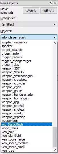
Click anywhere on the ground to add our custom entity. Observe a green box protruding from the floor where you clicked.
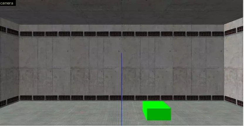
Its green because in our FGD we set the color to (0 255 0) The size of this box should also be what you had set in the FGD.
Select the Selection Tool.

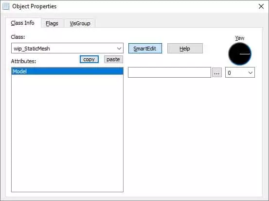
Either Right Click on the instance of the “wip_StaticMesh” entity, double click on it, or click on it and hit ALT + ENTER to bring up the properties page for your selection.
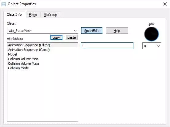
You should see something along these lines:
Let’s select a model for our entity. Since we have no models added to our mod yet we can grab one from Half-Life’s Valve/Model folder.
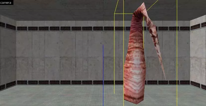
I select “tree.mdl” which is the Xen Tree from Half-Life
You should see the model update in jackhammer.
Note: There is no WYSIWYG Editor for GoldSrc or Source Games simply because the levels still need to be compiled and are only then loaded by the Engine. Recent Game Engine adaptations such as UE4, CryEngine & Unity use an instance of the Engine as the Level Editor so you have a clear idea of that the end result will be.
For example, if you loaded tree.mdl like I did you will notice that it is currently animated in the Editor but I know that it won’t animate in the game because I haven’t added code to my entity to handle that yet.
I will now play with the Yaw setting in the properties and set it to 180 so that the entity will face me.
The next step is to Compile the Map and Run it. This assumes that you have compiled your code to include your new entity.
If all went well you should see your custom entity loaded in the game.
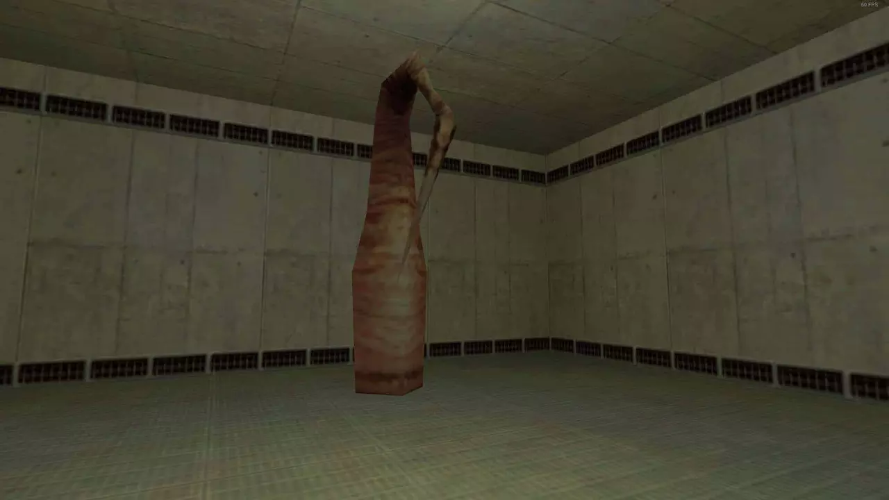
The GoldSrc Collison System
Now if you walk up to your entity hoping for it to present a realistic obstacle you will be sorely disappointed. We haven’t yet added code to utilize GoldSrc’s Collision system. The collision system in GoldSrc is based on the concept of AABB which stands for Axis Aligned Bounding Box. This means that all bounding boxes are locked to the orientation of the three axis of the world. Basically the bounding boxes cannot rotate in the same direction that the model is facing.
I assume this approach was used at the time for lack of a better solution and it is cheaper than other methods such as OOBB (Object oriented Bounding boxes). The following images demonstrate AABB better.
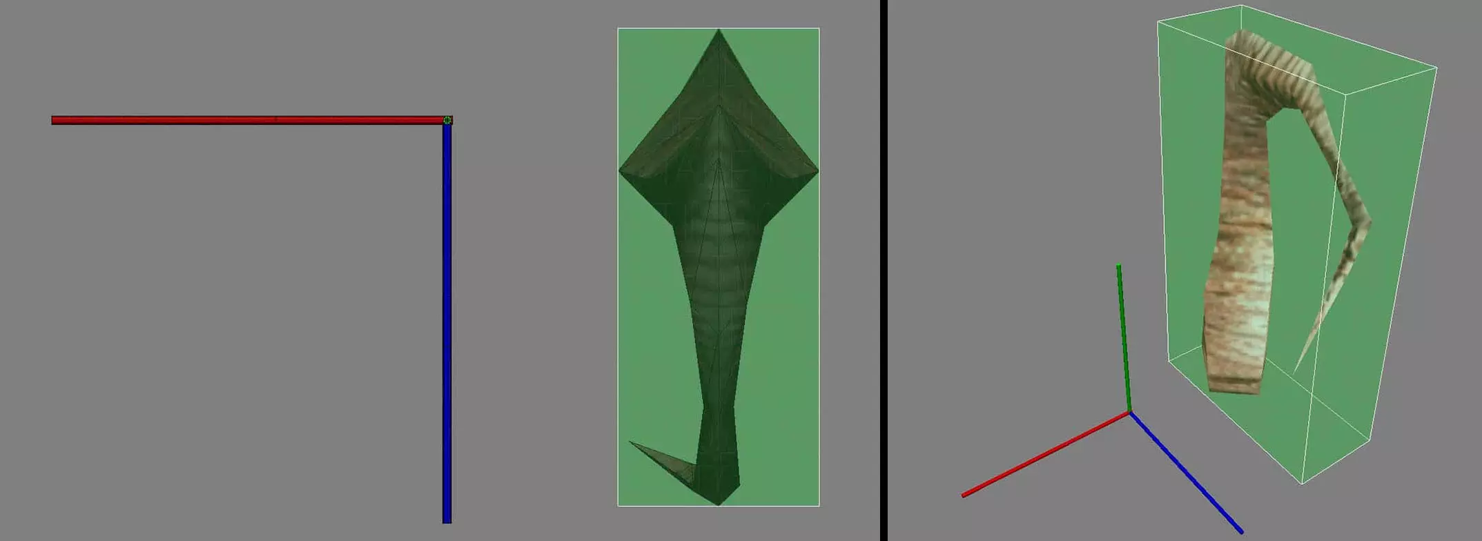
This shows a model which has no rotations on its local axis. The bounding box fits a little more naturally than below. For an Object Aligned Bounding Box system it would look the same since the model has no local rotation.
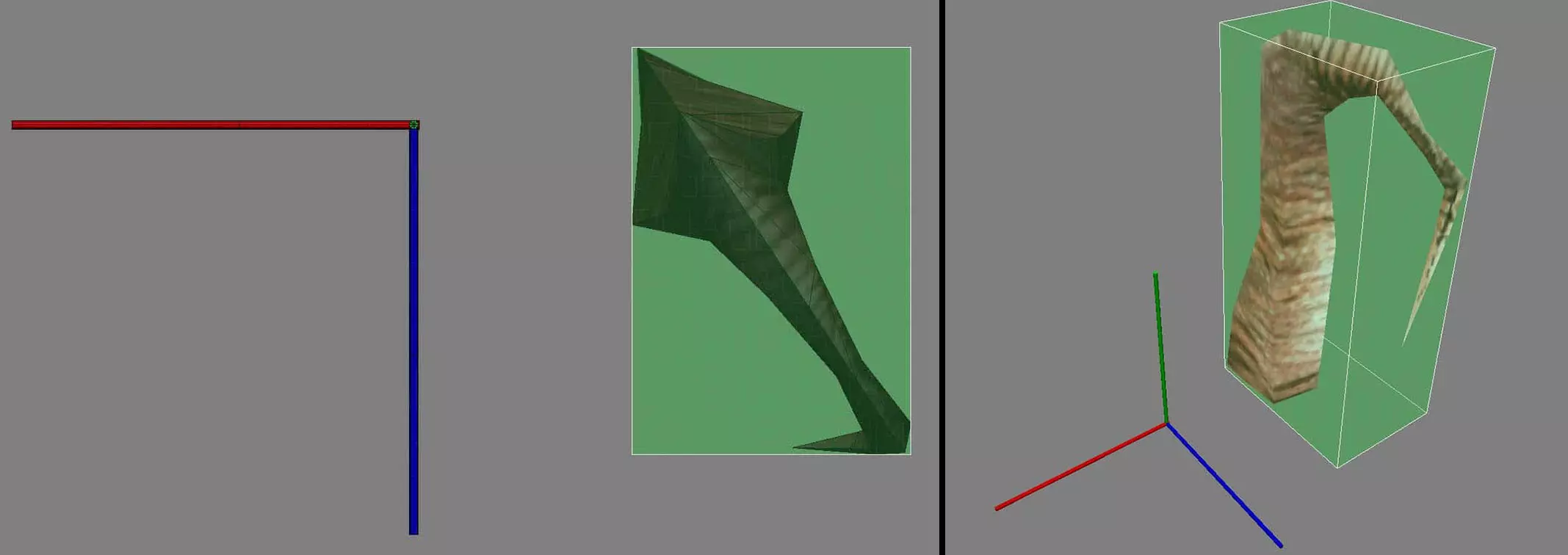
Here the Model has now been rotated about 45 degrees. The bounding box for an Axis Aligned system simply grows to encapsulate the whole model.
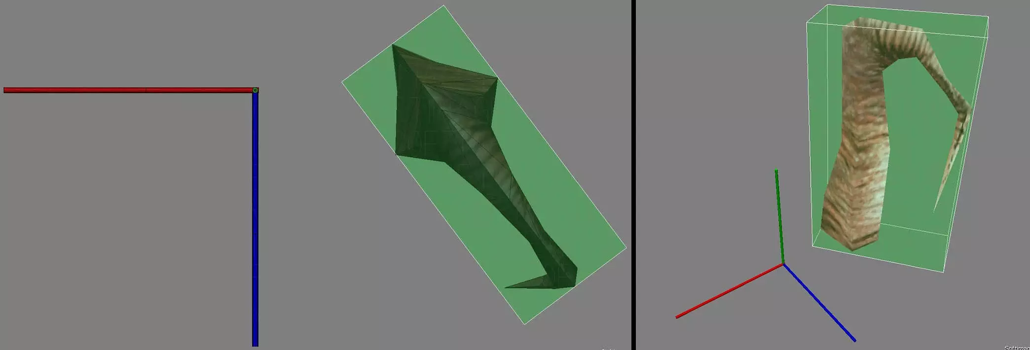
Here is what would happen on an OOBB system. The bounding box would follow the orientation of the model and would not stay locked to the world, and as a result it wouldn’t grow like it does in the AABB solution. This would be a nice system to have in GoldSrc but unfortunately it is not implemented and for the purposes of my mod it wouldn’t warrant an attempt to implement it. So for now we are stuck with AABB Collisions.
From what I have observed and learned of GoldSrc’s collision system is it depends greatly on how the entity that loads the model handles the size of the collision box. Either it will take the sizes set by the animation loaded by the model (if any) or you can set a size through code.
Rotations are going to cause an issue simply because the bounding volumes cannot be rotated in an AABB system. This means that if we want our model to be completely encapsulated in a bounding volume it will be a very inaccurate representation of the already inaccurate collision box. To combat that I suggest we set a manual bounding volume for any static meshes we place and that we reduce the size and position of this box to underlap the model itself. Some clipping will occur in some cases but it would provide a better collision volume. We will explore this further on in the tutorial using the Xen Tree as our example model.
In our case what we will do is provide the user with an option to load the bounding box from the models currently running animation sequence which it will get from the mdl file itself or the user can manually enter a static size in hammer.
The GoldSrc Collison System
Let’s start by simply setting a hard coded size in Visual Studio and viewing the result in-game. The Function that sets the Collision volume for a model in GoldSrc is:
UTIL_SetSize(Entity, Vec3 Mins, Vec3 Maxs)It accepts a reference to the entity whose collision size you are setting, as well as two Vector 3 Objects for the Minimum XYZ Position and the Maximum XYZ Position of the Collision box.
In our Spawn Function lets add the following:
pev->solid = SOLID_BBOX;
UTIL_SetSize(pev, Vector(-32, -32, 0), Vector(32, 32, 32));
//                 Mins    X    Y  Z    Maxs   X   Y   Z
pev->solid must be set to SOLID_BBOX otherwise we will still be able to walk through it even with UTIL_SetSize() set. We will make this a selectable Flag in Hammer for those who want to clip static meshes.
Other Flags this can be set to include:
#define	SOLID_NOT		0	// no interaction with other objects
#define	SOLID_TRIGGER	1	// touch on edge, but not blocking
#define	SOLID_BBOX		2	// touch on edge, block
#define	SOLID_SLIDEBOX	3	// touch on edge, but not an onground
#define	SOLID_BSP		4	// bsp clip, touch on edge, block
For the UTIL_SetSize() function note that you can set the mins to a negative value. Compile the Code and enter your test level once again. You should notice that when you try to walk through your mesh the player steps up slightly. That is because we made a square 64W * 64L * 32H at the models origin. We set the mins Z to 0 to avoid the volume clipping downwards through the worlds ground.
To briefly explain how the min and max values are used to create a bounding volume, see the following description.
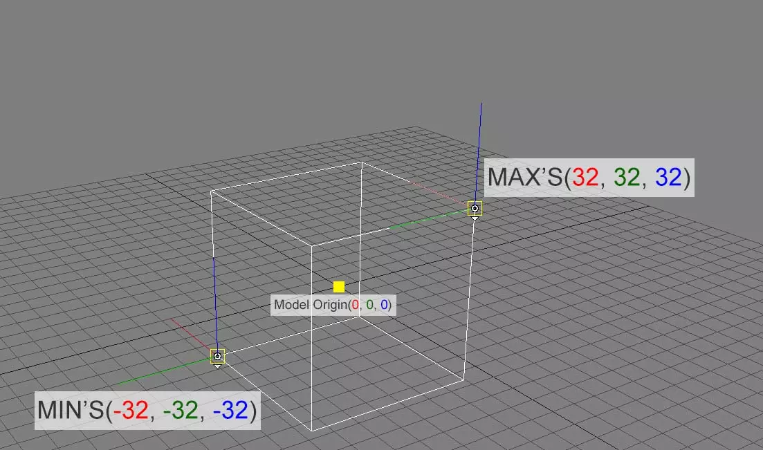
UTIL_SetSize(pev, Vector(-32, -32, -32), Vector(32, 32, 32));Bounding boxes for models in GoldSrc are bound to the local position of the model. So in the case above where we provide Mins of -32, -32, -32 that means -32 units on all axis from the models local 0,0,0 position, not the models world position. The Maxs are 32, 32, 32 on all axis which means +32 on all axis from the models local position.
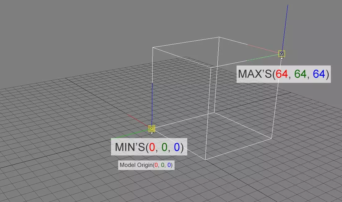
UTIL_SetSize(pev, Vector(0, 0, 0), Vector(64, 64, 64));Here we set the Mins to 0, 0, 0 which is the same as the models local position and the Maxs to 64, 64, 64 along each axis. This in most cases (unless the model is offset) will give for an undesirable amount of collision coverage as only a quarter of the model (depending on the models shape) would be covered.
GoldSrc then takes the Mins and Maxs and constructs a Cube from the given value.
The GoldSrc Collison System
Currently we cannot see the bounding box but let’s change that by creating the UTIL_RenderBBox() function.
Add the following function to our Util.h file:
// Foo BBox Rendering
void UTIL_RenderBBox(Vector origin, Vector mins, Vector maxs, int life, BYTE r = 0, BYTE b = 0, BYTE g = 0);
And then add the function to the end of util.cpp
void UTIL_RenderBBox(Vector origin, Vector mins, Vector maxs, int life, BYTE r, BYTE b, BYTE g)
{
	//********************Render boundrybox**************************

	MESSAGE_BEGIN(MSG_BROADCAST, SVC_TEMPENTITY);

	WRITE_BYTE(TE_BOX);
	// coord, coord, coord boxmins
	WRITE_COORD(origin[0] + mins[0]);
	WRITE_COORD(origin[1] + mins[1]);
	WRITE_COORD(origin[2] + mins[2]);

	// coord, coord, coord boxmaxs
	WRITE_COORD(origin[0] + maxs[0]);
	WRITE_COORD(origin[1] + maxs[1]);
	WRITE_COORD(origin[2] + maxs[2]);
	WRITE_SHORT(life); // short life in 0.1 s (1min)
	WRITE_BYTE(r); // r, g, b
	WRITE_BYTE(g); // r, g, b
	WRITE_BYTE(b); // r, g, b

	MESSAGE_END(); // move PHS/PVS data sending into here (SEND_ALL, SEND_PVS, SEND_PHS)
}
After that, we will need an update function which GoldSrc presents to us through the Think Function.
Note: If you want your model to update on a frame by frame (or a custom amount) basis you will need a Think function. We can set this function using the SetThink(&ReferenceToCustomThinkFunction). We will be setting Animate(void) as the Think Function for our Mesh Loader Class.
Add the Animate function to the header file.
class CStaticMesh : public CBaseAnimating
{
private:
	void Spawn(void);
	void EXPORT Animate(void);
};Note: If I remember correctly the EXPORT Macro is used to export the symbols to the DLL such that the game can query its state between save games. Functions that use this are SetThink, SetUse, SetTouch, SetBlocked. When we save a game in GoldSrc, the Engine is queried for the symbolic name for these functions, when we load the save game the Engine simply has to look up this symbolic name and restore the state.
Let’s add this Animate function to the source CPP file. Simply add it after void CStaticMesh::Spawn(void)
void CStaticMesh::Animate(void)
{
	pev->nextthink = gpGlobals->time + 0.01;
UTIL_RenderBBox(pev->origin, pev->mins, pev->maxs, 1, 0, 255, 0);
}
pev->nextthink is basically a time in the future when you will call the Think Function again for this Class which in this case is Animate. We set pev->nextthink to the current time plus 0.01. Adding a larger number to the end would mean that the animate function would be re-called less frequently and the opposite for an even smaller number.
The function we added earlier will provide a visual representation of our bounding box.
UTIL_RenderBBox(Entity, Mins, Max’s, Lifetime, ColorR, ColorB, ColorG);
This function accepts a reference to our Entity, The Mins and Maxs of the box you want to render (we provide the same mins and maxs we gave the Bounding Box).
The Lifetime controls how long the representation renders for. (doesn’t seem to work as expected) The last three parameters control the RBG values of the visualization (yes that’s right RBG not RGB)
We have one further change to make to our Spawn() function in order to enable our Think function. Add the following at the end of the Spawn function:
SetThink(&CStaticMesh::Animate);
pev->nextthink = gpGlobals->time + 0.01;
Here we set our local Animate function to be used as the Think Function by the Engine. Again we set the next think slightly into the future. In this case it is only called once as it’s the spawn function, The Animate function will henceforth handle all updates.
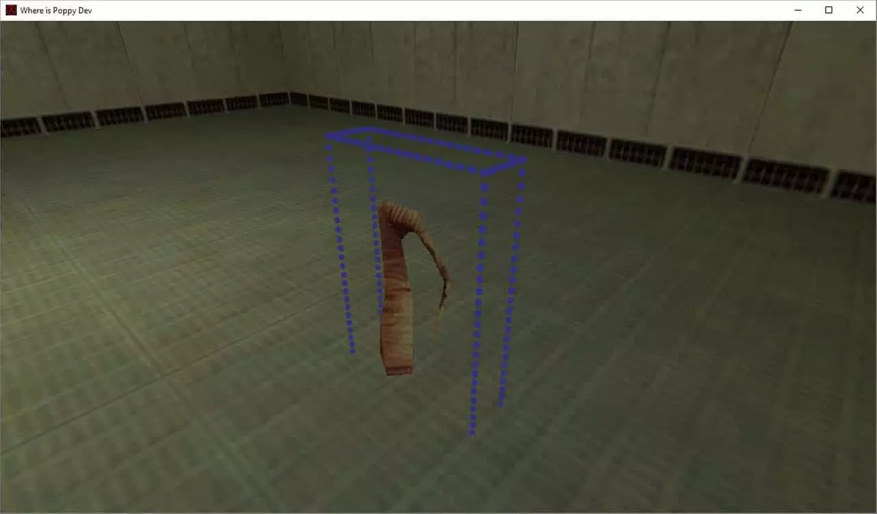
Compile your code and run the game. You should see something like this:
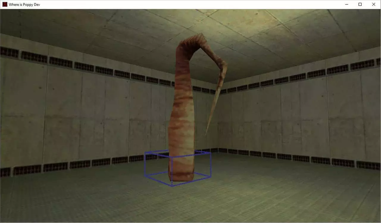
Now if I was to change the Mins in the UTIL_SetSize to 0,0,0 like so:
UTIL_SetSize(pev, Vector(0, 0, 0), Vector(32, 32, 32));Observe the affect it has on the Collision Volume:
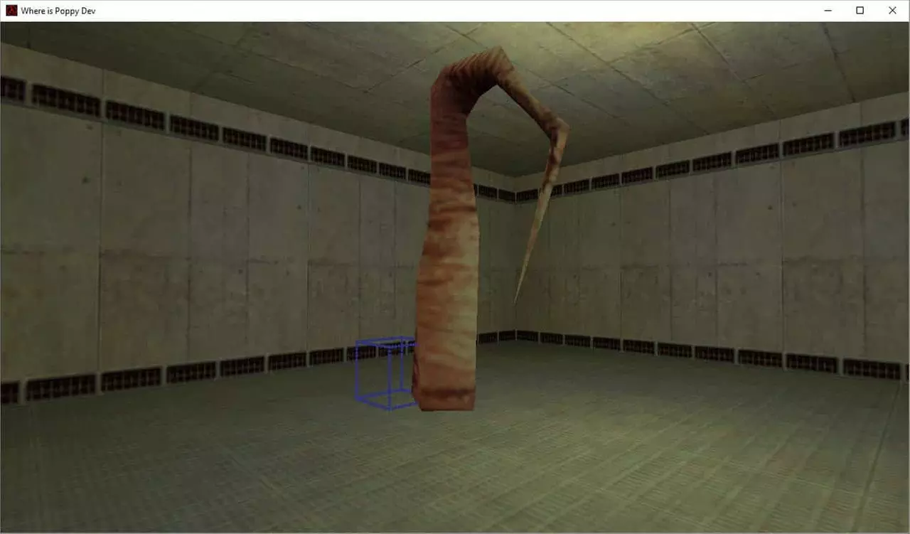
t may look like the bounding volume is rendering down the negative axis but in fact recall that we had rotated our model 180 degrees. The bounding volume is not at all affected by the rotation of the Mesh. So with that in mind notice that the Mins are positioned exactly on the pivot or root of this model.
You will need to keep in mind that if you want your model encapsulated by your collision mesh set at least the X and Y values of the Mins Vector to the negative version of the Max’s X and Y Vector.
A suitable Value I see for this particular Model is the following:
UTIL_SetSize(pev, Vector(-32, -32, 0), Vector(32, 32, 190));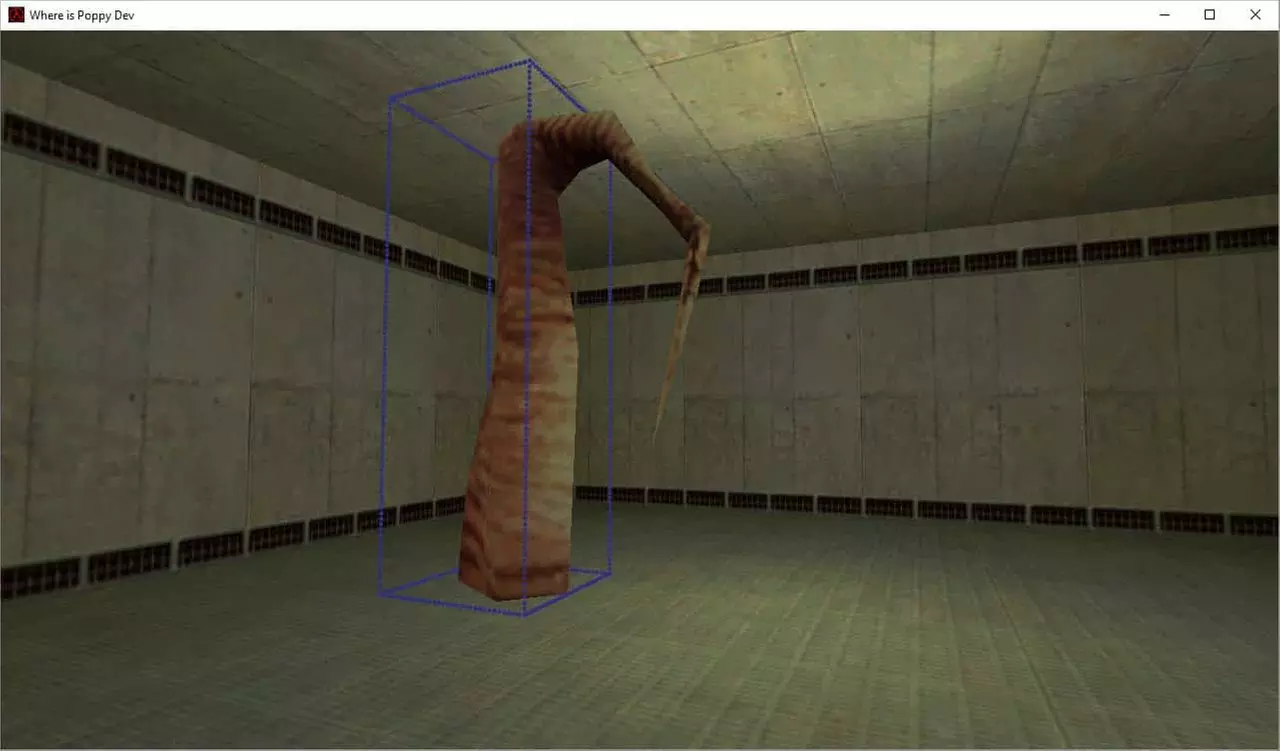
The next step is to make this currently static function a little more modular so that the user can set the Min and Max values in Hammer and have those values used on object spawn.
Manually set Collision Volume
Let’s add the following two lines to our Header:
void KeyValue(KeyValueData *pkvd);
Vector mins, maxs;
The Header should now look like this:
class CStaticMesh : public CBaseAnimating
{
private:
	void Spawn(void);
	void EXPORT Animate(void);
	void KeyValue(KeyValueData *pkvd);
Vector mins, maxs;
};
KeyValue will be the function to read specific non standard elements from the compiled Map for use in our entities code. We also declare Vector variables for our min and max values so that we can modify and set them between functions in our class. Next we must modify our Spawn function once again.
We must replace our UTIL_SetSize() Function
UTIL_SetSize(pev, Vector(-32, -32, 0), Vector(32, 32, 190));with:
UTIL_SetSize(pev, maxs, mins);The whole Spawn function should now look like this:
void CStaticMesh::Spawn(void)
{
	PRECACHE_MODEL((char *)STRING(pev->model));
	SET_MODEL(ENT(pev), STRING(pev->model));

	pev->solid = SOLID_BBOX;
	UTIL_SetSize(pev, mins, maxs);

	SetThink(&CStaticMesh::Animate);
	pev->nextthink = gpGlobals->time + 0.01;
}
Next up let’s make the KeyValue Function. You can add it anywhere in your CPP file.
void CStaticMesh::KeyValue(KeyValueData *pkvd)
{
	if (FStrEq(pkvd->szKeyName, "bbmins"))
	{
		UTIL_StringToVector(mins, pkvd->szValue);
		pkvd->fHandled = TRUE;
	}
	else if (FStrEq(pkvd->szKeyName, "bbmaxs"))
	{
		UTIL_StringToVector(maxs, pkvd->szValue);
		pkvd->fHandled = TRUE;
	}
	else
		CBaseEntity::KeyValue(pkvd);
}
Basically this function is called before our spawn function to gather values set inside our map. We will need to make changes to our FGD and map shortly.
We are setting the min Vector to a string value which will be set on the “bbmins” FGD Key. The same will happen to the maxs Vector which will be set to the “bbmaxs” key value.
We use a very useful function to convert a string to a vector called UTIL_StringToVector(Vector, String) It turns the String “32 64 51” into the Vector(32, 64, 51) Add bbmins and bbmaxs to our FGD file with default Values.
// Where is Poppy Forge Game Data
// Cathal McNally
// sourcemodding@gmail.com
// www.sourcemodding.com
// February, 2017
// wip_StaticMesh
@PointClass color(0 255 0) size(-20 -20 -20, 20 20 20) studio() = wip_StaticMesh : "wip_StaticMesh"
[
model(studio) : "Model"
bbmins(string) : "Collision Volume Mins" : "-16 -16 -16"
bbmaxs(string) : "Collision Volume Maxs" : "16 16 16"
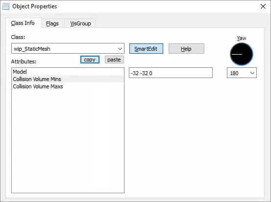
]Restart Hammer and open the properties for our wip_staticMesh Entity.
Add 3 space separated Values to the Collision Volume Mins Parameter. “-32 -32 0”
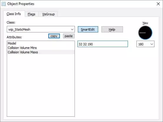
Add 3 space separated Values to the Collision Volume Maxs Parameter. “32 32 190”
Compile the Map and the Code. Then run the Game to see your bounding box using the values you input through Hammer.
Solid Flag
Next we will add what is known as a flag which can also be set in Hammer. This is basically a condition which we will use in code to check if we should enable Collisions at all.
Firstly, let’s add the following to our header:
#define WIP_IS_SOLID 1This will be used as an identifier to check if the first flag set on the properties is true or false. If this was set to 2 we would be checking the second flag etc.
Next is to make some changes in our spawn function. We must wrap a condition around our pev->solid and UTIL_SetSize lines.
It will look like this:
if (FBitSet(pev->spawnflags, WIP_IS_SOLID))
{
	pev->solid = SOLID_BBOX;
	UTIL_SetSize(pev, mins, maxs);
}
This checks the boolean state of the given Flag. In this case we are passing the first flag and only if it’s true will the entity be set to solid and a size set.
The last thing we need to do to make this work is to add the spawnflags to the FGD
spawnflags(flags) =
[
    1: "Solid?" : 1
]
The “1” key above corresponds to the 1 we set WIP_IS_SOLID to. “Solid?” is what the flag will be called in hammer. The last “1” is the default value which in hammer will translate to true.
Save the FGD and restart Hammer to load in the new FGD Values.
There should be a new flag on the Flags tab of the wip_staticMesh properties.
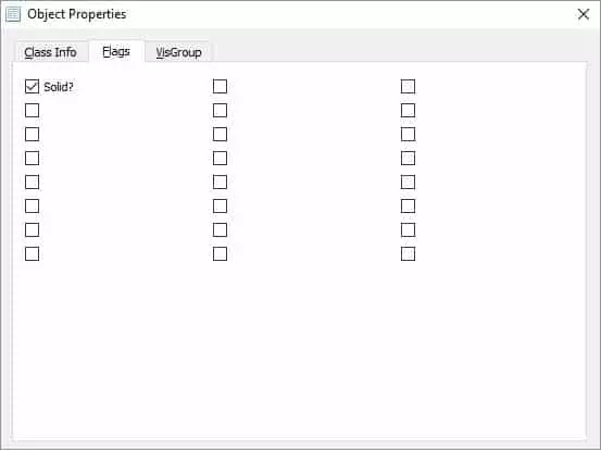
Set it to true, compile the map, compile the code and test your level. You should still be blocked by the collision box.
Set it to false and you should be able to pass clean through your model.
Sequence based Collision
Next up we add the ability for the user to decide if they want to use Sequence based Collisions or Manually input Values for Collision.
Firstly, lets add this to our header.
unsigned short m_iCollisionMode;Note: I made this a short because it is cheaper than a full integer type, and unsigned because it should never be a negative value.
It will be used for a multi choice selection within Hammer and then checked in our spawn function upon which we will use either a sequence based collision box or our previously added manual values for a collision box.
The function used to set our mins and maxs from a sequence is:
ExtractBbox(Sequence Number, mins, maxs)This function will look up the local entity that owns the current instance of the class, grab the sequence that we set as an integer and populate two Vectors which in this case will be mins and maxs.
In our Spawn function let us change this:
if (FBitSet(pev->spawnflags, WIP_IS_SOLID))
{
	pev->solid = SOLID_BBOX;
	UTIL_SetSize(pev, mins, maxs);
}
to:
// Check if the Solid Flag is set and if so be sure to set it
// solid with appropriate Collisions
// If not we also do not set a Collision Box because for a static mesh
// there is no reason to do so..
if (FBitSet(pev->spawnflags, WIP_IS_SOLID))
{
	pev->solid = SOLID_BBOX;

 	if (m_iCollisionMode == 1)
	{
		UTIL_SetSize(pev, mins, maxs);
	}
	else if (m_iCollisionMode == 2)
	{
		ExtractBbox(0, mins, maxs);
		UTIL_SetSize(pev, mins, maxs);
	}
}
Note that we are setting the sequence to 0 here, we will be providing a future option shortly for users to input what sequence they want their model to play.
Then we must modify our KeyValue function to read in a value for m_iCollisionMode
Change the following:
void CStaticMesh::KeyValue(KeyValueData *pkvd)
{
	if (FStrEq(pkvd->szKeyName, "bbmins"))
	{
		UTIL_StringToVector(mins, pkvd->szValue);
		pkvd->fHandled = TRUE;
	}
	else if (FStrEq(pkvd->szKeyName, "bbmaxs"))
	{
		UTIL_StringToVector(maxs, pkvd->szValue);
		pkvd->fHandled = TRUE;
	}
	else
		CBaseEntity::KeyValue(pkvd);
}
to include it:
void CStaticMesh::KeyValue(KeyValueData *pkvd)
{
	if (FStrEq(pkvd->szKeyName, "collisionmode"))
	{
		m_iCollisionMode = atoi(pkvd->szValue);
		pkvd->fHandled = TRUE;
	}
	else if (FStrEq(pkvd->szKeyName, "bbmins"))
	{
		UTIL_StringToVector(mins, pkvd->szValue);
		pkvd->fHandled = TRUE;
	}
	else if (FStrEq(pkvd->szKeyName, "bbmaxs"))
	{
		UTIL_StringToVector(maxs, pkvd->szValue);
		pkvd->fHandled = TRUE;
	}
	else
		CBaseEntity::KeyValue(pkvd);
}
Lastly we need to add our multi-option to our FGD.
collisionmode(choices) : "Collision Mode" : 2 =
[
	0: "None"
	1: "Manual Inputs"
	2: "Sequence Based"
]
Save your FGD and restart hammer.
You should now see a multi-option choice box as part of the entities properties.
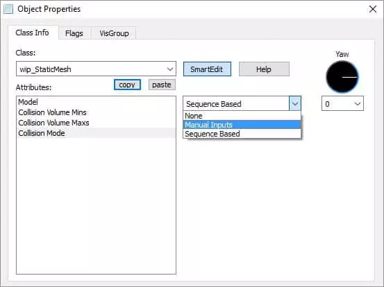
I then setup two entities in hammer one using Manual Inputs where I use Mins of (-32, -32, -32) and Maxs of (32, 32, 32) so our collision box should be a distinctive cube.
The other entity will use sequence based collision and as we have set the sequence to 0 in the code it will use this models first sequence as a collision box.
Note: It’s important to remember that if the Solid Flag is not set in the Flags tab, no collision values will work and no collision box will be set even if you set the values here. This is used to optimize spawn times for static meshes that do not require collision volumes.
This is how it looks.
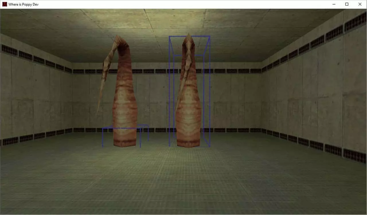
The tree to the left uses the manually set collision while the tree to the right uses the models first sequence bounds as a collision volume.
The Issue of Rotation and Collisions with an AABB System
As you can see above the bounding Volume does not rotate with our model which has been rotated 180 on the z axis. The best solution to this would be to implement OOBB Collisions but that is far beyond the scope of this tutorial and is honestly not required.
I propose using manual inputs for bounding volumes on models of these type. Consider this:
Create a tall volume centred around the models pivot so that when the model rotates the main shaft of this particular model is covered. It’s not perfect but AABB is far from a perfect collision system, we work with what we have.
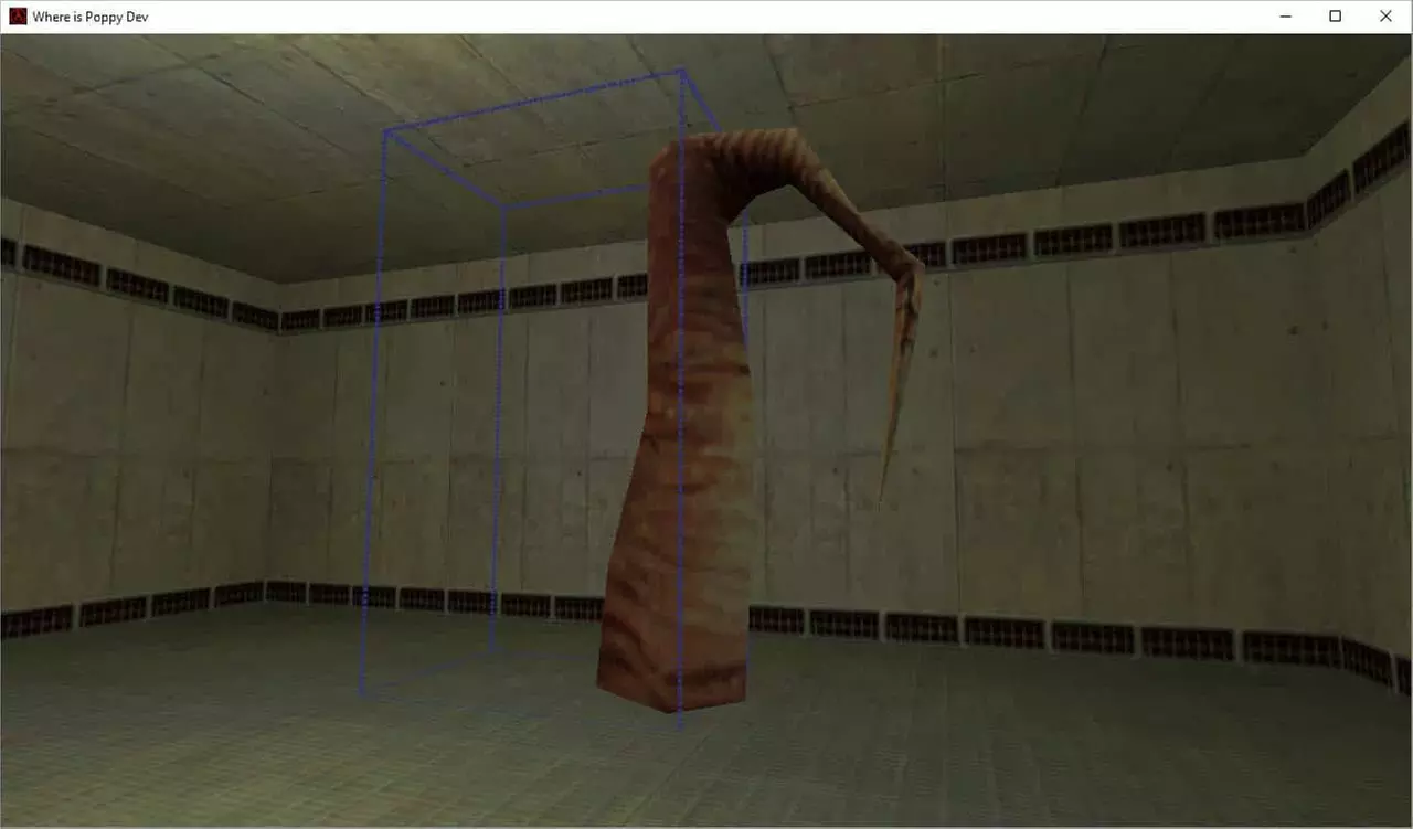
Consider a model that is longer in width or length than it is in height. I will rotate the tree model on its side to demonstrate this. You could not use the sequence based collisions at all, you can use the manual inputs for angles that are multiplies of 90 degrees.
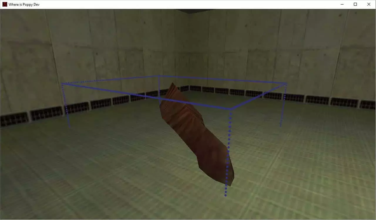
I rotate the model in hammer with the following values.
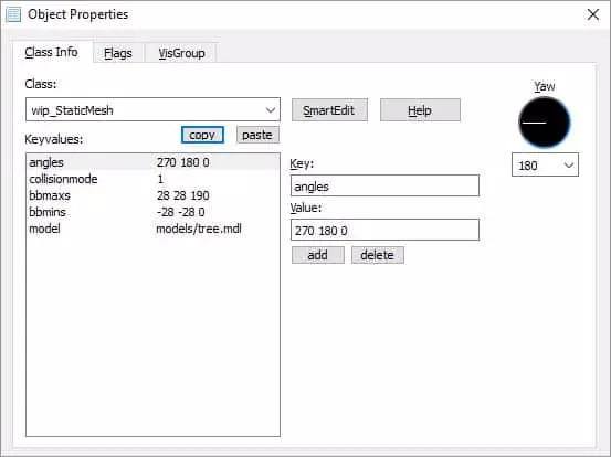
It then looks like this:
I then set the Mins to -190 -28 -28 and the Maxs to 0 28 28 and the result can be seen below.
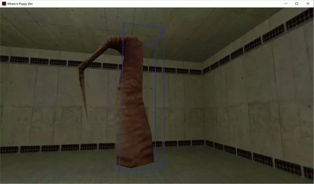
If I rotate the model 90 degrees, I would need to update the mins and maxs to cover it again. So long as the models local orientation looks directly down one of the world’s axis you will be able to make some sort of useable collision volume for it.
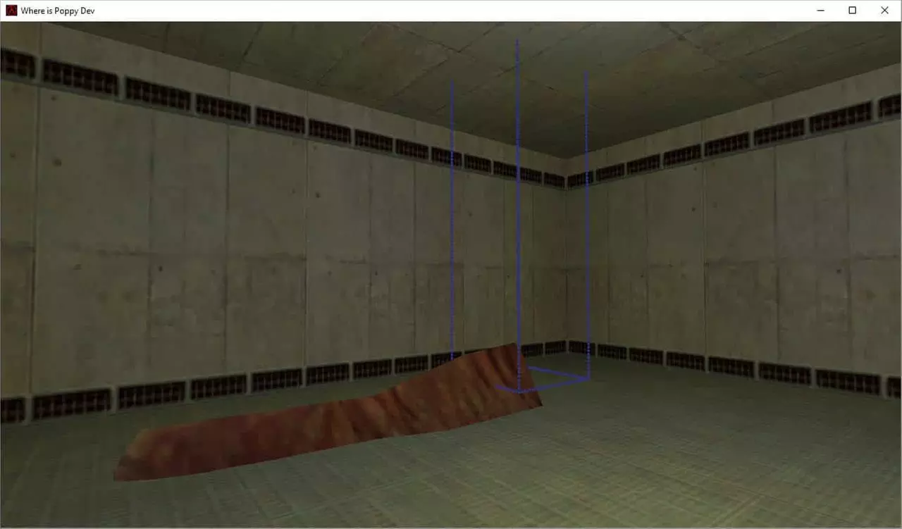
However, when the model is rotated anywhere between 90 degree steps you have the following issue when you update the mins and maxs to cover the model.
The mins and maxs used to get this are: Mins -130 -145 -28 Maxs 0 28 28
And as you can see it is a woefully inaccurate collision box.
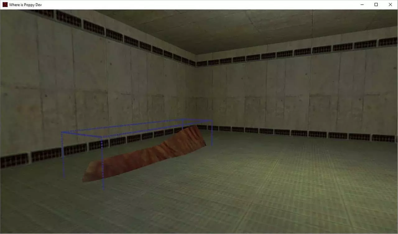
To work around this, I propose you disable collision on a model with these rotations and orientation and use invisible BSP geometry (CLIP Brush) to build smaller colliders along the model which is assumed to be static.
They would look something like this:
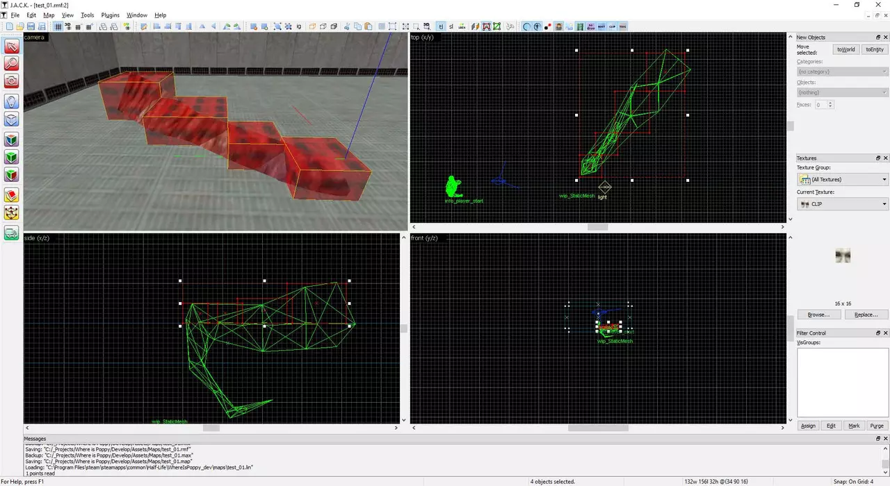
The CLIP Brush is basically a static block with the CLIP Material applied to it. It renders the geometry with the Material applied to it as invisible but prevents the user from walking through it, similar to “player clip” in Source.
It’s obviously far from a perfect solution but it’s a decent workaround.
Keep in mind that you could always use a CLIP brush instead of manually entering Mins and Maxs for the models own collision model.
Bounding Box Visualization Aid
The last change I want to make regarding collision is giving the user the choice whether they want to render the bounding box visualization around their model or not.
Let’s first add another Flag to our header and set it to 2 (The second flag in the Flags Tab) and a Boolean that we will use in our animate function to enable or disable the bounding box visualizer.
bool m_bDebugBB = false;

#define WIP_DEBUG_BB 2
Next change the following in our spawn function:
if (FBitSet(pev->spawnflags, WIP_IS_SOLID))
{
	pev->solid = SOLID_BBOX;

	if (m_iCollisionMode == 1)
	{
		UTIL_SetSize(pev, mins, maxs);
	}
	else if (m_iCollisionMode == 2)
	{
		ExtractBbox(0, mins, maxs);
		UTIL_SetSize(pev, mins, maxs);
	}
}
to this:
if (FBitSet(pev->spawnflags, WIP_IS_SOLID))
{
	pev->solid = SOLID_BBOX;

	if (m_iCollisionMode == 1)
	{
		UTIL_SetSize(pev, mins, maxs);
	}
	else if (m_iCollisionMode == 2)
	{
		ExtractBbox(0, mins, maxs);
		UTIL_SetSize(pev, mins, maxs);
	}

	if (FBitSet(pev->spawnflags, WIP_DEBUG_BB)){
		m_bDebugBB = true;
	}
}
We do the WIP_DEBUG_BB check within the WIP_IS_SOLID check because we don’t need to visualize the bounding box when our model won’t be solid.
We carry out the flag check in the spawn function and set the Boolean m_bDebugBB to true. We do this because it’s cheaper than doing an FBitSet check in our animate function every frame. This way we will only have to check the Boolean value every time the animate function is called.
Change the Animate function from:
void CStaticMesh::Animate(void)
{
	pev->nextthink = gpGlobals->time + 0.01;
	UTIL_RenderBBox(pev->origin, pev->mins, pev->maxs, 1, 0, 255, 0);
}
to:
void CStaticMesh::Animate(void)
{
	pev->nextthink = gpGlobals->time + 0.01;
	if (m_bDebugBB){
		UTIL_RenderBBox(pev->origin, pev->mins, pev->maxs, 1, 0, 255, 0);
	}
}
Then in the FGD add the “Debug Bounding Box?” flag to our spawnflags:
spawnflags(flags) =
[
	1: "Solid?" : 1
	2: "Debug Bounding Box?" : 0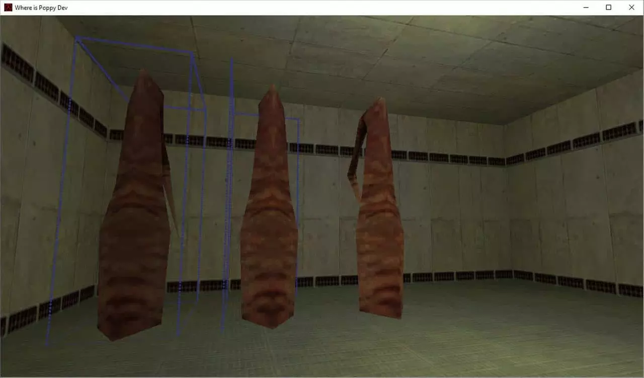
]Note: The UTIL_RenderBBox function seems to be limited in how many lines it can render, Probably an engine limit. See the following screen shot to explain what I mean; I have multiple entities loaded in the map with the WIP_DEBUG_BB Flag set to true. The last model (rightmost) I added does not render any Bounding Box Visualization and the second model (middle) only renders some of the lines of the Bounding volume.
r_drawentities 5
Those of you familiar with the r_drawentities Console variable know that it provides 4 rendering modes for entities in game.
- Don’t render any entities
- Default, Render an Entity in its normal state
- Render an Entities Skeleton if it has one
- Render an Entities HitBoxes
- Render an Entities Hitboxes translucent with the Model underneath
In GoldSrc’s Software rendering mode there was a 5th option which quite helpfully renders the bounding volume based on the Models currently running sequence only. It will not render a bounding volume of a custom set Size so for that the UTIL_RenderBBox will provide an accurate representation in that case.
To enable this feature in the OpenGL Renderer we have a small change to make to StudioModelRenderer.cpp
Locate the StudioRenderFinal_Hardware Function and add the following condition:
// Lets add bounding boxes to the OpenGL Renderer too!
if (m_pCvarDrawEntities->value == 5)
{
IEngineStudio.StudioDrawAbsBBox();
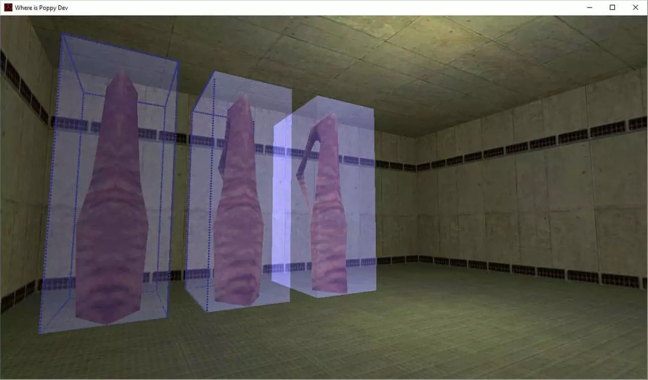
}You can see that I borrowed it directly from the StudioRenderFinal_Software function. As to why this was exclusive to the Software Renderer I do not know but I suspect it was simply not supported by OpenGL in the late 90’s. You can compile the code and enter r_drawentities 5 to see the transparent blue representation of the currently selected sequence Bounding Box (Remember that we hardcoded it to 0 earlier as part of our ExtractBbox function)
You might wonder why we want to include animation with something that is supposed to be an inanimate static object? There may be situations for instance where we use this loader for a plant or a bush which could include a sway animation to mimic movement in the wind.
Let’s add to our header file an integer to hold the id for what animation our currently loaded model should be playing. I add it to the end of our other unsigned short for ease of use and reuse of code.
unsigned short m_iCollisionMode, m_iSequence;Next let’s add to the KeyValue Function so that it reads in the correct value for the animation sequence.
if (FStrEq(pkvd->szKeyName, "animate"))
{
	m_iSequence = atoi(pkvd->szValue);
	pkvd->fHandled = TRUE;
}
The whole function should now look like this:
void CStaticMesh::KeyValue(KeyValueData *pkvd)
{
	if (FStrEq(pkvd->szKeyName, "animate"))
	{
		m_iSequence = atoi(pkvd->szValue);
		pkvd->fHandled = TRUE;
	}
	else if (FStrEq(pkvd->szKeyName, "collisionmode"))
	{
		m_iCollisionMode = atoi(pkvd->szValue);
		pkvd->fHandled = TRUE;
	}
	else if (FStrEq(pkvd->szKeyName, "bbmins"))
	{
		UTIL_StringToVector(mins, pkvd->szValue);
		pkvd->fHandled = TRUE;
	}
	else if (FStrEq(pkvd->szKeyName, "bbmaxs"))
	{
		UTIL_StringToVector(maxs, pkvd->szValue);
		pkvd->fHandled = TRUE;
	}
	else
		CBaseEntity::KeyValue(pkvd);
}
We must then set the sequence based on what the user input through hammer. We do that in the Spawn function near the end. We must add the following:
pev->sequence = m_iSequence;Another small change we should make while we are in the Spawn function is to change this:
ExtractBbox(0, mins, maxs);to:
ExtractBbox(m_iSequence, mins, maxs);This makes sure that the correct sequence Collision box will be used if the user selects to use that collision mode.
We then need to add the following to our Animate function so that the animation can play.
pev->frame > 255 ? pev->frame = 0 : pev->frame++;For those unfamiliar with the above line it is known as a ternary operation, basically an inline if else statement. Its written like this simply as an arguably easier alternative which is a little faster to write.
The equivalent as an if else would be:
if (pev->frame > 255){
	pev->frame = 0;
}else{
	pev->frame++
}
Basically we are just making sure that the frames are incrementing with each update and if we reach the max of 255 reset to zero and start incrementing again.
pev->frame controls the individual frames in a sequence.
We must change our FGD from:
@PointClass color(0 255 0) size(-20 -20 -20, 20 20 20) studio() = wip_StaticMesh : "wip_StaticMesh"
[
	model(studio) : "Model"
	bbmins(string) : "Collision Volume Mins" : "-16 -16 -16"
	bbmaxs(string) : "Collision Volume Maxs" : "16 16 16"
	spawnflags(flags) =
    [
        1: "Solid?" : 1
        2: "Debug Bounding Box?" : 0
    ]
  	collisionmode(choices) : "Collision Mode" : 2 =
	[
		0: "None"
		1: "Manual Inputs"
		2: "Sequence Based"
	]
]
to:
@PointClass color(0 255 0) size(-20 -20 -20, 20 20 20) studio() = wip_StaticMesh : "wip_StaticMesh"
[
	sequence(integer) : "Animation Sequence (Editor)" : 0 : "Sequence to display in Jackhammer. This does not affect gameplay."
	animate(integer) : "Animation Sequence (Game)" : 0 : "Setting an in game Animation Sequence for the selected model"
	model(studio) : "Model"
	bbmins(string) : "Collision Volume Mins" : "-16 -16 -16"
	bbmaxs(string) : "Collision Volume Maxs" : "16 16 16"
	spawnflags(flags) =
    [
		1: "Solid?" : 1
		2: "Debug Bounding Box?" : 0
    ]
    collisionmode(choices) : "Collision Mode" : 2 =
	[
		0: "None"
		1: "Manual Inputs"
		2: "Sequence Based"
	]
]
We use the following to set a sequence that we can visualize in the editor, for some reason this does not work for actually setting the value we would expect to see in game and that’s why we have a separate animate key. I believe that the word “sequence” is reserved much like the keys “mins” and “maxs”. I could not for the life of me get them to work.
sequence(integer) : "Animation Sequence (editor)" : 0 : "Sequence to display in Jackhammer. This does not affect gameplay."And finally we use the following to set what sequence will actually be used in game
animate(integer) : "Animation Sequence (Game)" : 0 : "Setting an in game Animation Sequence for the selected model"Save the FGD, compile the code, restart Hammer and you should see 2 new entries in the properties of our entity.
The Editor Entry changes it for the editor and the Game Entry changes it in game so be sure to set the in game entry correctly if you intend to use animations.
Try the editor version and watch as your model plays the different animations you switch to. I highlight this option as an easy way to preview what sequence you play and its totally optional, rip it out if you don’t need it.
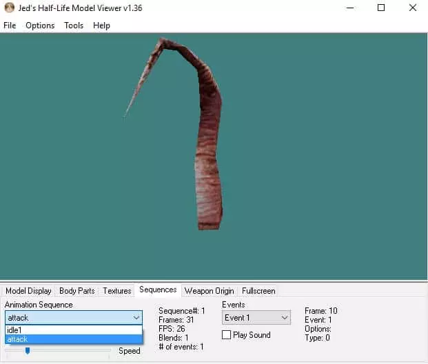
If you load tree.mdl into JHLMV note that you have two animations to choose from. A sequence number is given to be used as an ID/Index, this is the number you provide in hammer to select a Sequence.
This current implementation does not provide for people who do not want to play animations. So let’s prepare a Flag and a condition in the code to cater for this.
Change the following to our header:
bool m_bDebugBB = false;to:
bool m_bDebugBB = false, m_bAnimate = false;And add the following after that:
I explain why I use the value 4 and not 3 below.
#define WIP_ANIMATE 4Next in our CPP change the following in our Spawn Function:
pev->sequence = m_iSequence;to:
// Check if the User wants to animate
if (FBitSet(pev->spawnflags, WIP_ANIMATE))
{
	m_bAnimate = true;
	pev->sequence = m_iSequence;
}
Then in our Animate function change:
pev->frame > 255 ? pev->frame = 0 : pev->frame++;to:
if (m_bAnimate){
	pev->frame > 255 ? pev->frame = 0 : pev->frame++;
}
Again this is cheaper to check a Boolean in the update loop as opposed to checking the state of the Flag which involves calling further functions.
Add the following to our flags section in the FGD
4: "Animate?" : 1Note: that I skip the number 3 here and in the header which seems to be a feature/bug/limit in how flags work or are sent between the FGD and the game or between the Map and the game. Flags are stored as a power of 2. So the series to set them goes like this 1, 2, 4, 8, 16, 32, 64, 128, 256 etc.
All the spawn flags together should now look like this:
spawnflags(flags) =
[
     1: "Solid?" : 1
     2: "Debug Bounding Box?" : 0
     4: "Animate?" : 1
]
Save the FGD, Compile the code, restart hammer and check out our new flag in the entities properties flags tab.
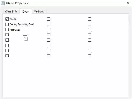
Test your changes with the flag enabled and observe the inanimate model within our seen.
Let’s also add a speed variable to our entity to control how fast the model’s sequence plays back in game.
Add the following float to our header
float m_flAnimationSpeed = 0.0f;Then add it to our KeyValue Function to read in its data. We use atof() not atoi()
if (FStrEq(pkvd->szKeyName, "animationspeed"))
{
	m_flAnimationSpeed = atof(pkvd->szValue);
	pkvd->fHandled = TRUE;
}
Let’s add it to our animate function where it will be used to set the animation speed. Note: 1.0 = normal speed, Greater than 1.0 = faster animation, we will use a negative number to change the direction of the animation, which involves a little extra coding.
Let’s change:
if (m_bAnimate){
	pev->frame > 255 ? pev->frame = 0 : pev->frame++
}
to:
if (m_bAnimate){
	if (m_flAnimationSpeed >= 0.0){
		pev->frame > 255 ? pev->frame = 0 : pev->frame += m_flAnimationSpeed;
	}
	else{
		pev->frame < 0 ? pev->frame = 255 : pev->frame += m_flAnimationSpeed;
	}
}
Basically what I am doing here is checking if we are animating, then I am checking our speed variable for what was input in the map, If it’s a positive number, we increment using the speed as the increment value If it’s a negative number, we decrement using the speed as the decrement value effectively reversing the animation.
1.0 = normal forward animation speed, default
>1.0 = faster than normal speed, dependant on what you input
0.0 = No animation
<1.0 && > 0.0 = slower animation speed
<= -1 = reversed animation and a lower negative value gives faster reverse playback
You could argue against my animate flag here (and use the animation speed condition instead) since a value of 0.0 for the animation speed means the model wont animate either but I wanted to also show you that flag id’s were powers of 2.
Add our latest addition to the FGD:
animationspeed(string) : "Animation Speed" : "1.0"Restart hammer, check the new property and test out both positive and negative values.
The last major addition I want to bring to our entity is the ability to scale our mesh.
This does not work out of the box for meshes in GoldSrc as the support was only built in for sprites. However, we can make a small change to our client project which would enable pev->scale for meshes.
Locate in the hl_cdll project the file StudioModelRenderer.cpp.
In the function:
CStudioModelRenderer::StudioSetUpTransform (int trivial_accept)Towards the bottom lets add the following:
if (m_pCurrentEntity->curstate.scale != 0 && m_pCurrentEntity->curstate.scale != 1.0)
{
	for (int i = 0; i < 3; i++)
	{
		for (int j = 0; j < 3; j++)
		{
			(*m_protationmatrix)[i][j] *= m_pCurrentEntity->curstate.scale;
		}
	}
}
Basically this checks for a change in the models scale. The scale setting by default is 0 since it was unused prior to this. If its zero technically we shouldn’t see it so let’s not modify it if its zero.
A scale of 1 would also mean no change and the model would be its original scale baked into the mdl file.
Anything between those numbers require that the rotation matrix be modified by multiplying each value in the matrix by the scale input by the user through the hammer level.
Let’s tie it all together by returning to wip_static_mesh.h
Add the following float:
float m_fModelScale = 1.0f;Then we must also consider that we have to modify the collision boxes. We scale them by the same amount we scale the visible mesh.
Change the following:
if (FBitSet(pev->spawnflags, WIP_IS_SOLID))
{
	pev->solid = SOLID_BBOX;

 	if (m_iCollisionMode == 1)
	{
		UTIL_SetSize(pev, mins, maxs);
	}
	else if (m_iCollisionMode == 2)
	{
		ExtractBbox(m_iSequence, mins, maxs);
		UTIL_SetSize(pev, mins, maxs);
	}

	if (FBitSet(pev->spawnflags, WIP_DEBUG_BB)){
		m_bDebugBB = true;
	}
}
to:
if (FBitSet(pev->spawnflags, WIP_IS_SOLID))
{
	pev->solid = SOLID_BBOX;

 	if (m_iCollisionMode == 1)
	{
		mins = mins * m_fModelScale;
		maxs = maxs * m_fModelScale;

		UTIL_SetSize(pev, mins, maxs);
	}
	else if (m_iCollisionMode == 2)
	{
		ExtractBbox(m_iSequence, mins, maxs);

		mins = mins * m_fModelScale;
		maxs = maxs * m_fModelScale;

		UTIL_SetSize(pev, mins, maxs);
	}

	if (FBitSet(pev->spawnflags, WIP_DEBUG_BB)){
		m_bDebugBB = true;
	}
}

pev->scale = m_fModelScale;
We then modify KeyValue to include a check for the scale.
Add the following:
else if (FStrEq(pkvd->szKeyName, "modelscale"))
{
	m_fModelScale = atof(pkvd->szValue);
	pkvd->fHandled = TRUE;
}
Finally let’s add to the FGD
modelscale(string) : "Model Scale (Game)" : "1.0" : "Set the Model Scale (0.0 - 1.0)"
scale(string) : "Model Scale (Editor)" : "1.0" : "Set the Model Scale (0.0 - 1.0)"
Again the word “scale” seems to be reserved and won’t pass values to the game engine so we use “scale” for the editor and “modelscale” for ingame scale changes.
Save the FGD, Compile the Code, make scale changes in Hammer and load the game to see a scaled Mesh. If you enable the bounding box visualizer and set the collision mode to sequence you can see the collision box scale perfectly with your model.
Here is a xen tree scaled by 0.2:
I noticed during development of this entity two scenarios one of which could be hard to detect and debug.
They both relate to loading the mesh itself.
If the model you are trying to load does not exist, the game will throw a precaching error and tell you which model is missing.
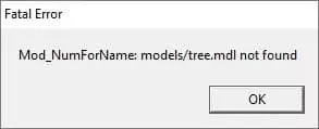
That’s useful enough in this case because you know what model is missing so you can simply locate and fix the issue.
The other issue causes a crash with no error and occurs if you create an instance of our entity but do not apply a model file to it.
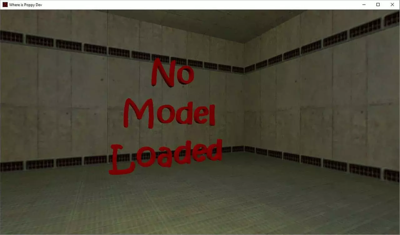
To avoid this crash, I have made a small null.mdl model which says no model loaded and I use the defaults parameter in the FGD to set this model.
That way when you set the model in hammer you will see this null.mdl instead of a solid box.
model(studio) : "Model" : "models/null.mdl" : "Set a Mesh to load into the Game"I placed this custom model in my Mods model folder.
Its looks like this:
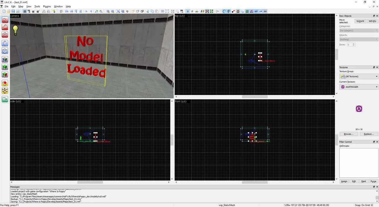
Without our custom null.mdl set it would look like this:
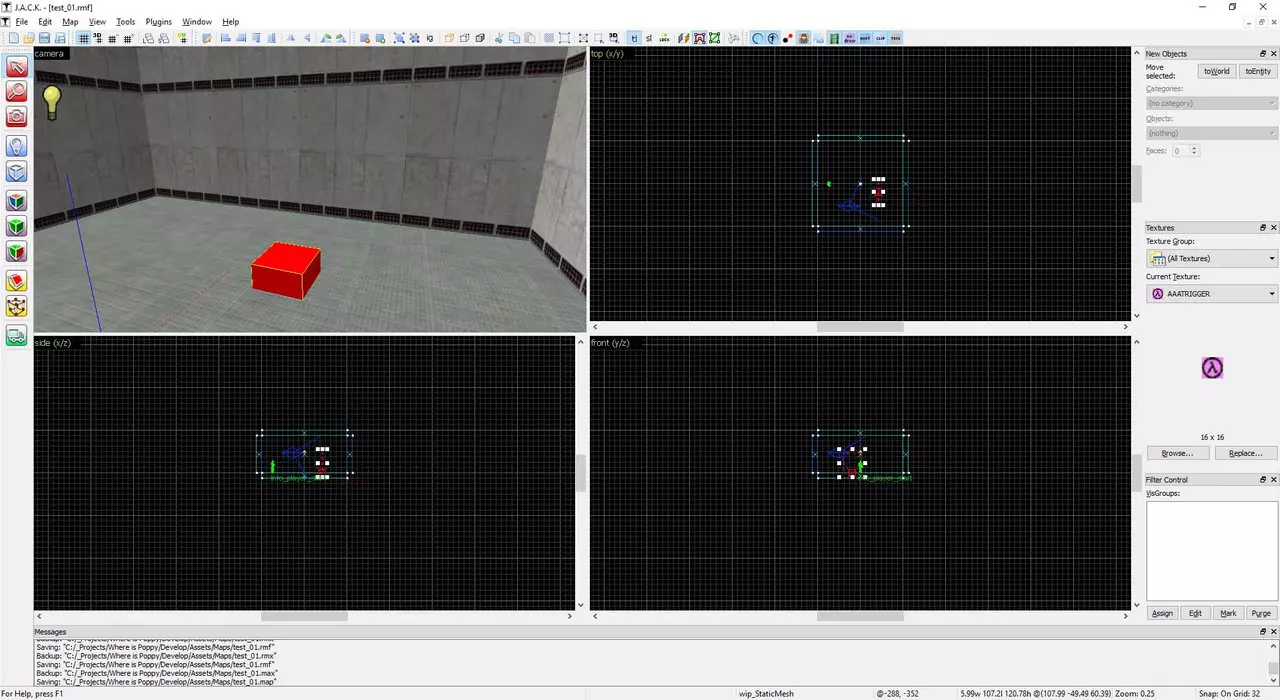
And would cause a crash.
To avoid the crash let’s make a small change to the following code:
Change:
PRECACHE_MODEL((char *)STRING(pev->model));
SET_MODEL(ENT(pev), STRING(pev->model));
to:
if (pev->model != 0){
	PRECACHE_MODEL((char *)STRING(pev->model));
	SET_MODEL(ENT(pev), STRING(pev->model));
}
else{
	ALERT(at_console, "[wip_staticMesh] Error, Model Failed to load!\n");
	ALERT(at_console, "[wip_staticMesh] Setting model/null.mdl in its place!\n");
	PRECACHE_MODEL("models/null.mdl");
	SET_MODEL(ENT(pev), "models/null.mdl");
}
So now even if the user removes the defaults from the entity to force the error we will always load the null.mdl (provided it hasn’t been removed) to visualize that a model is missing.
I have also made some changes to the header file to account for the possibility that some variable might be used and haven’t yet been set to a value. To do this is simply assign each to a default value.
Header
/******************************
Where is Poppy
29.8.2016

wip_static_mesh.h

Static Mesh Loader for the mod
Where is Poppy

*******************************/

#ifndef WIP_STATIC_MESH_H
#define WIP_STATIC_MESH_H

#include "extdll.h"		// Required for KeyValueData
#include "util.h"		// Required Consts & Macros
#include "cbase.h"		// Required for CPointEntity

class CStaticMesh : public	CBaseAnimating
{
private:
	void Spawn(void);
	void EXPORT Animate(void);
	void KeyValue(KeyValueData *pkvd);

	Vector mins = { 0, 0, 0 },
		   maxs = { 0, 0, 0 };

	unsigned short m_iCollisionMode = 0,
				   m_iSequence = 0;

	bool m_bDebugBB = false,
		 m_bAnimate = false;

	float m_flAnimationSpeed = 1.0f,
		  m_fModelScale = 1.0f;

	#define WIP_IS_SOLID 1
	#define WIP_DEBUG_BB 2
	#define WIP_ANIMATE  4
};

#endif
Source CPP
/******************************
Where is Poppy
February, 2017

wip_static_mesh.cpp

Static Mesh Loader for the mod
Where is Poppy

*******************************/

#include "wip_static_mesh.h"

// Need to Link our class to the name (wip_StaticMesh) that hammer will read from the FGD.
// This will be linked directly to the level as well so that the engine can link to it.
LINK_ENTITY_TO_CLASS(wip_StaticMesh, CStaticMesh);

///////////////////////////////
// Spawn(void)
//
// The Spawn function handles the creation and intialization of our entitty
// It is the second function to run in this Class
////////////////////////////////
void CStaticMesh::Spawn(void)
{
	// Precache and Load the model
	if (pev->model != 0){
		PRECACHE_MODEL((char *)STRING(pev->model));
		SET_MODEL(ENT(pev), STRING(pev->model));
	}
	// If the Model doesnt exist, print an error and set a default null.mdl as the model
	else{
		ALERT(at_console, "[wip_staticMesh] Error, Model Failed to load!\n");
		ALERT(at_console, "[wip_staticMesh] Setting model/null.mdl in its place!\n");
		PRECACHE_MODEL("models/null.mdl");
		SET_MODEL(ENT(pev), "models/null.mdl");
	}

	// Check if the Solid Flag is set and if so be sure to set it
	// solid with appropriate Collisions
	// If not we also do not set a Collision Box because for a static mesh
	// there is no reason to do so..
	if (FBitSet(pev->spawnflags, WIP_IS_SOLID))
	{
		// Set Model solid
		pev->solid = SOLID_BBOX;

		// Check the collision mode 0 = None, 1 = Manual, 2 = Sequence based
 		if (m_iCollisionMode == 1)
		{
			// Scale the collision box
			mins = mins * m_fModelScale;
			maxs = maxs * m_fModelScale;

			// Set Collision box Size
			UTIL_SetSize(pev, mins, maxs);
		}
		else if (m_iCollisionMode == 2)
		{
			// Grab Bounding box size from current sequence
			ExtractBbox(m_iSequence, mins, maxs);

			// Sacle the collision box
			mins = mins * m_fModelScale;
			maxs = maxs * m_fModelScale;

			// Set Collision box Size
			UTIL_SetSize(pev, mins, maxs);
		}

		// Check if the bounding box Visualizer flag is set
		if (FBitSet(pev->spawnflags, WIP_DEBUG_BB)){
			m_bDebugBB = true; // If so set this value to true, we using it in Animate()
		}
	}

	// Set the visible meshes scale
	pev->scale = m_fModelScale;

	// Check if the User wants to animate
	if (FBitSet(pev->spawnflags, WIP_ANIMATE))
	{
		m_bAnimate = true; // Used in Animate()
		pev->sequence = m_iSequence; // Set the animation based on what the user set in the level
	}

	// Set our update/think function to Animate()
	SetThink(&CStaticMesh::Animate);
	// Set when in the future to update next
	pev->nextthink = gpGlobals->time + 0.01;
}

///////////////////////////////
// KeyValue(KeyValueData *pkvd)
//
// The KeyValue function imports values set by our level editor in our map
// These Keys are created in our FGD
// We set local variables to the values that the map returns when requested
// It is the first function to run in this Class
////////////////////////////////
void CStaticMesh::KeyValue(KeyValueData *pkvd)
{
	// Grab the speed our animation plays at
	// 0.0 here also stops the animation
	// A netagive value plays the animation in reverse
	// A higher value speeds up the animation
	if (FStrEq(pkvd->szKeyName, "animationspeed"))
	{
		m_flAnimationSpeed = atof(pkvd->szValue);
		pkvd->fHandled = TRUE;
	}
	// In-Game version of editor only variable "sequence"
	// Set an integer to what sequence you want this model to play ingame
	else if (FStrEq(pkvd->szKeyName, "animate"))
	{
		m_iSequence = atoi(pkvd->szValue);
		pkvd->fHandled = TRUE;
	}
	// Set a mode for Collision
	// 0 = No Collision
	// 1 = Manual Mins & Maxs
	// 2 = Sequence Based Collision
	else if (FStrEq(pkvd->szKeyName, "collisionmode"))
	{
		m_iCollisionMode = atoi(pkvd->szValue);
		pkvd->fHandled = TRUE;
	}
	// Minimum Bounding box position
	else if (FStrEq(pkvd->szKeyName, "bbmins"))
	{
		UTIL_StringToVector(mins, pkvd->szValue);
		pkvd->fHandled = TRUE;
	}
	// Maximum Bounding box position
	else if (FStrEq(pkvd->szKeyName, "bbmaxs"))
	{
		UTIL_StringToVector(maxs, pkvd->szValue);
		pkvd->fHandled = TRUE;
	}
	// Set the scale of our model and collision boxes
	// In-Game version of the editor only "scale" keyword
	else if (FStrEq(pkvd->szKeyName, "modelscale"))
	{
		m_fModelScale = atof(pkvd->szValue);
		pkvd->fHandled = TRUE;
	}
	// defaults
	else
		CBaseEntity::KeyValue(pkvd);
}


///////////////////////////////
// Animate(void)
//
// The Animate function is basically the Update function of this Entitiy
// You add thinks here that you want to change on a frame by frame basis
// Things like animations
// Position changes
// Interactive code
////////////////////////////////
void CStaticMesh::Animate(void)
{
	// Set when in the future to next run the animate function
	pev->nextthink = gpGlobals->time + 0.01;

	// If animation is allowed
	if (m_bAnimate)
	{
		if (m_flAnimationSpeed >= 0.0)
		{
			// Ternary condition to update the models normal animation + any extra speed the user adds
			pev->frame > 255 ? pev->frame = 0 : pev->frame += m_flAnimationSpeed;
		}
		else
		{
			// Ternary condition to update the models reverse animation + any extra speed the user adds
			pev->frame < 0 ? pev->frame = 255 : pev->frame += m_flAnimationSpeed;
		}
	}
	// Visualize the Collision Volume around the model
	if (m_bDebugBB){
		UTIL_RenderBBox(pev->origin, pev->mins, pev->maxs, 1, 0, 255, 0);
	}
}
FGD
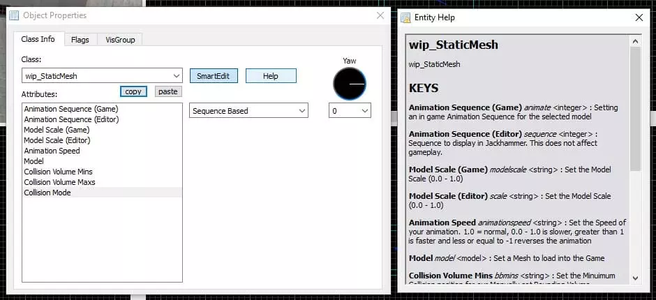
In case you hadn’t noticed FGDs support a default value as well as the option to include a short description of what the function does. For Example:
// Key(type)  : Name    : Default Value   : Description of function

model(studio) : "Model" : "path/to/model" : "Select a Model to Load"

sequence(integer) : "Animation Sequence (editor)" : 0 : "Sequence to display in Jackhammer. This does not affect gameplay."
I cleaned up the FGD to include descriptions which can be shown in the help section of the Entity in Hammer.
// Where is Poppy Forge Game Data
// Cathal McNally
// sourcemodding@gmail.com
// www.sourcemodding.com

// 29.8.2016

// wip_StaticMesh

@PointClass color(0 255 0) size(-20 -20 -20, 20 20 20) studio() = wip_StaticMesh : "wip_StaticMesh"
[
	animate(integer) : "Animation Sequence (Game)" : 0 : "Setting an in game Animation Sequence for the selected model"
	sequence(integer) : "Animation Sequence (Editor)" : 0 : "Sequence to display in Jackhammer. This does not affect gameplay."
	animationspeed(string) : "Animation Speed" : "1.0" : "Set the Speed of your animation. 1.0 = normal, 0.0 - 1.0 is slower, greater than 1 is faster and less or equal to -1 reverses the animation"
	modelscale(string) : "Model Scale (Game)" : "1.0" : "Set the Model Scale (0.0 - 1.0)"
	scale(string) : "Model Scale (Editor)" : "1.0" : "Set the Model Scale (0.0 - 1.0)"
	model(studio) : "Model" : "models/null.mdl" : "Set a Mesh to load into the Game"
	bbmins(string) : "Collision Volume Mins" : "-16 -16 -16" : "Set the Minuimum Collision position for our Manually set Bounding Volume"
	bbmaxs(string) : "Collision Volume Maxs" : "16 16 16" : "Set the Maximum Collision position for our Manually set Bounding Volume"
	spawnflags(flags) =
    [
        1: "Solid?" : 1 : "Enable Collisions?"
        2: "Debug Bounding Box?" : 0 : "Show a visual representation of the bounding box?"
        4: "Animate?" : 1 : "Animate the Model?"
    ]
    collisionmode(choices) : "Collision Mode" : 2 =
	[
		0: "None" : "No Collisions"
		1: "Manual Inputs" : "Enter Manual Min and Max values for a Custom Bounding Volume?"
		2: "Sequence Based" : "Take the Bounding volume from the selected Animation Sequence?"
	]
]
Click on Help in our object properties. The help tips in hammer for our entity looks like this: